BUGSYS(ID:246/bug001)
Pattern based animation language
from BUG SYStem (system was derived from L6, which had BUGs as a basic data structure
Pattern recognition and preparing movies from photo stills, for IBM 7094 and IBM 360.
People: Hardware:
- IBM 709 IBM
Related languages
| L6 | => | BUGSYS | Extension of | |
| Scanner | => | BUGSYS | Evolution of |
Samples:
References:
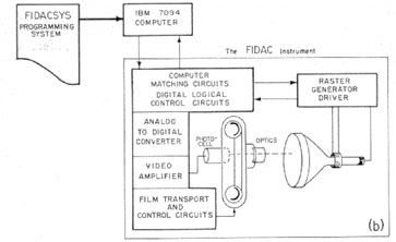
The biological and medical scientist has developed highly specialized and precise techniques for photographing structures, forms, and phenomena that occur in almost every field of biomedi-cal research. Huge masses of material are accumulating at an ever-increasing rate, such as photomicrographs of chromosomes that relate to genetic diseases; photomicrograph sequences showing the dendritic structure of nerve cells; electron micrographs of muscle fiber structure and of DNA with bases containing radioactive heavy atoms; and films of x-ray diffraction patterns of biologically important molecules. Individual pictures hold a great wealth of precise numerical information, such as morphological and structural characteristics of lengths, areas, volumes, densities; from sequences of pictures quantitative results can be derived, such as kinematic and dynamic characteristics of trajectories, velocities, and accelerations. The large-scale quantitative analysis of these pictures cannot be achieved by manual methods, because of the tedium, manual precision, and extensive time that is necessarily involved. Hence we have embarked on a program designed to enable such pictures to be analyzed automatically by means of a digital computer. The technique described in this paper promises to open up entirely new fields of investigation in biological and medical research (7). There are two main steps in this technique: first, a scanning instrument called FIDAC (Film Input to Digital Automatic Computer) "reads" the picture on-line into the high-speed memory of a digital computer; second, a computer programming system, called FIDACSYS, "recognizes" the object to be measured and processes the quantitative data according to requirements of the particular biological or medical problem under consideration. The FIDAC system was designed specifically for the processing of biomedical pictures.
The FIDAC instrument is responsible in the first place for putting the picture into the computer's memory; it is an on-line computer-input device which can scan in real-time at very high speed and with high resolution with computer-program feedback control (see Fig. 1). FIDAC has (i) a high-speed scan of less than 0.2 second per frame, which makes possible the rapid processing of pictures for statistical analysis and screening purposes; (ii) a high resolution (greater than that of the optical microscope), enabling all information to be retained when it is scanning photomicrographs—that is, for a magnification of 1000 each 0.2 /x of the specimen is sampled by more than three points (2); (iii) the capability of realtime operation, enabling program control of the FIDAC by the computer— that is, when the processing of a film frame has been completed, the program
signals the FIDAC to move automatically to the next frame; and (iv), direct input to the computer—this results in extreme flexibility, convenience, and economy of storage of the original data (3). During the scan, over 800,000 points per picture (1,000 X 800 point raster) are sampled in the black-and-white mode, one memory bit per picture point being used, or over 350,000 points per picture (700 X 500 point raster) are sampled in the eight-level gray mode, three memory bits being used (4). As a comparison, FIDAC can load the computer's core memory 10 to 50 times faster than can conventional magnetic-tape input units. In fact the speed of the scan and the number of points per picture that are sampled are presently limited not by the FIDAC device, but rather by the large-scale high-speed computer being used [that is, by the cycle-time and size of the magnetic core memory (5)]. The new generation of computers, with higher speed and larger memories, will be able to take further advantage of the capabilities of the FIDAC instrument (6). This resolution and scanning speed holds for 16-mm movie frames, 35-mm movie frames, and 35-mm slide frames.
Extract: The FIDACSYS Programming System
The FIDACSYS Programming System
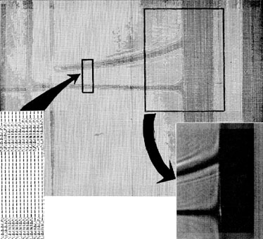
Once the picture is recorded in the computer's core memory, as a grid of points each with one of eight gray-level values (see Fig. 2), the computer analysis proceeds by means of the FIDACSYS programming system. This
system consists of a large number of basic computer programs integrated with each other in different ways for different problems; in effect, the system constitutes a general pattern-recognition and analysis programming language.
in Science, 146(3641) October 9, 1964. view details
in Science, 146(3641) October 9, 1964. view details
A BUGS statement creates the necessary housekeeping to keep track of the current intensity level and location of each named pointer. The named pointers ("bugs") are manipulated by the commands PLACE (the named bug is placed at a specific spot with rectangular coordinates x, y); MOVE (the named bug is moved a specified number of locations vertically or horizontally); CENTER (the named bug Centered on the line currently covered; the center statement also allows for an intensity level cutoff to define the thickness of the line, and logical branching if the thickness exceeds a specified limit); CHANGE (the intensity level of the spot covered by the named bug is changed); TEST (allows branching on the intensity level of the spot currently covered by the named bug), and a GO TO branch is also provided. Thus curves, defined by areas of limited width and intensity levels contrasting to adjoining areas, may be traced and measured point by point by calling FORTRAN II compatible subroutines. The tracing output is by computer printout of the final intensity levels of the array of processed spots using numbers 1 through 6 and dots for the bug "footprints."
The advantages, in terms of language design, of using such a shaded term as BUG for a programmable cursor are not elucidated. However, perhaps the term may have some deep import for those who are entomological sophisticates.
in ACM Computing Reviews 7(03) May-June 1966 view details
in [AFIPS] Proceedings of the 1966 Spring Joint Computer Conference SJCC 28 view details
in [AFIPS] Proceedings of the 1966 Spring Joint Computer Conference SJCC 28 view details
Automatic picture processing by a computer has many and varied aspects, such as the analysis and measurement of pictorial patterns, the construction of picture sequences, the recognition of character shapes, the development of perspective figures, and so forth. For these applications various programming systems were developed.
In this paper one such system called BUGSYS is described, which is based on and evolved from the previous programming systems of Knowlton and of the authors. BUGSYS is a picture processing and measuring system t h a t depends upon a pictorial input to the computer's memory. For the picture input the FIDAC (Film Input to Digital Automatic Computer) scanning instrument has been used. FIDAC can sample 350,000 spots (700 × 500 raster) of a picture in eight grey levels (3 bits per spot), and record these directly in the core memory of an IBM 7094 computer within 0.3 seconds online and in real time. As soon as the picture has been recorded in the computer's memory, the picture processing by BUGSYS is carried out.
BUGSYS can be used for many types of applications. In particular, the authors have used the system for the analysis of photomicrographs of neuron dendrites and for the processing of Schlieren photographs taken for molecular weight determination when using ultracentrifuges. From a processing point of view, the problem is to make measurements on a curve. Since the lines are thick, the measurements must be made from points in the middle of the lines.
Thus, for example, in Figure 2 the middle of segment A - A ' defines the line X = 0, and the middle of segment B - B ' defines the line Y = 0. Hence a point on the curve, say the middle of the segment C-C', will have the X- and Y-coordinates illustrated. Many hours are presently required to make the measurements accurately by manual means, whereas the automatic computer analysis using BUGSYS can accomplish the same task within a fraction of a second for an entire photograph. Extract: The System
The System
The main concept of the system is the use of a collection of programmable pointers, which are visualized as a family of "bugs" (whence is derived the title of this paper). A bug can be initiated or PLACEd, and once initiated, a bug can be MOVEd. In addition a bug can change the grey-level value of the spot on which it may be located and it can lay down a so-called STICK across a <thick> line in the picture as an aid to locating the middle of the line. This system has other macros which enable a bug to test the grey level value of the spot on which it is located and which enables some program manipulation.
For each bug initialized by means of the macro PLACE, there is associated a list which gives the X- and Y-coordinates of the current position of that bug, the equivalent core location, the spot position (0-11) within this location (there are 3 bits per spot or 12 spots per IBM 7094 computer word) and the grey-level value of the current position of the bug. For example, if the bug named "ZIPPY" were in the position indicated by the circle, then the list for ZIPPY would contain the following:
| Address | Contents | Comment |
| ZIPPY<l> | 6 | x |
| ZIPPY<2> | 8 | y |
| ZIPPY<3> | 6009 | 5553 <first location of picture + 456 |
| ZIPPY<4> | 6 | (57 words per line times y) + 0 |
| ZIPPY<5> | 4 | (x divided by 12 spots per word and truncated to an integer) remainder of x divided by 12 grey-level value or contents of spot |
As a bug is moved about the picture by a program, the list for the bug is kept current. In fact, in essence, the list is the bug.
We now proceed to describe some of the statements of the BUGSYS language and then follow with an illustrative program written in the language.
PLACE
The PLACE statement initiates or sets up a bug by assigning a name and initial coordinates to it. The syntax is:
| <bug name> | ::= <FORTRAN label> |
| <coordinate> | ::= <unsigned integer>|<integer variable> |
| <x-coordinate> | ::= <coordinate> |
| <y-coordinate< | ::= <coordinate> |
| <PLACE statement> | ::= PLACE <bugname>, <x-coordinate>, <y-coordinate> |
BUGS
The BUGS statement allocates five storage locations to each bug named:
| <list> | ::= <bug name>|<list>, <bug name> |
| <BUGS statement> | ::= BUGS <list> |
MOVE
The MOVE statements move the bug a specified distance <i.e. number of spots> in either the x or the y directions, i.e. horizontally or vertically. The syntax is:
| <distance> | ::= <unsigned integer>|<integer variable> |
| <direction> | ::= LEFT|RIGHT|UP|DOWN |
| <MOVE statement> | ::= MOVE <bug name>, <direction>, <distance> |
The effect of the execution of "MOVE bugname,RIGHT, distance" is to move the bug to a new location having the same y-coordinate but a new x-coordinate as follows:
<new x-coordinate> = <present x-coordinate> + <distance>
"MOVE bugname,LEFT,distance" is similar, but distance is subtracted from the present x-coordinate. The list corresponding to <bugname> is adjusted for the new value accordingly, of course. This statement includes a two-way branch, for provision must be made to be sure that the bug will not be MOVEd out of the picture. Hence, if the bug would be moved out of the picture, then it is not moved at all, and the next sequential statement is taken as the next executed statement. Otherwise <i.e., if the bug would still be in the picture after the move> the bug is MOVEd and the next sequential statement is skipped.
GO TO
For facilitating the two-way branch, a GO TO statement is included in the system, with syntax as follows:
| <GO TO statement> | ::= GO TO <FORTRAN label> |
TEST
A series of statements are included in the system that TEST the grey-level value of the picture at the location of the bug. The syntax of three of them is as follows:
| <grey cutoff> ::= | 0|1|2|3|4|5|6|7 |
| <relation> ::= | EQUAL|GREATR|LESSN |
| <TEST statement> ::= | TEST <bug name>, <relation>, <grey cutoff> |
For "TEST bugname,EQUAL,grey cutoff," if the grey level value of the picture at the location of the bug is not equal to <grey cutoff>, then the next sequential statement is executed; otherwise <i.e., if the picture value is equal to the cutoff value> the next sequential statement is skipped.
For "TEST bugname, GREATR, grey cutoff," if the picture value is less than or equal to the cutoff value, then the next sequential statement is executed; otherwise <i.e., if the picture value is greater than the grey cutoff value> the next sequential statement is skipped.
CHANGE
A bug's grey-level value may be changed with the macro CHANGE:
| <CHANGE statement> | ::= CHANGE <bug name>, <grey cutoff> |
The grey cutoff, 7, is reserved as a control in order that the bug can leave sevens or "footprints" on the picture. This is an aid when checking out a BUGSYS program. The number, 7, can cause any user'specified symbol to be printed.
STICK
Statements that are particularly useful for "thick line" analysis are the STICKs. If a bug wishes to walk along the middle of a "thick line," these statements will readjust the bug location to the "middle" of the thick line. For example, suppose that the "thick line" is characterized by grey levels of 4 or greater, and that the present location <encircled> is not in the middle of the "thick line" <see Figure 3>. To adjust the bug's position, a horizontal stick is laid down to the right and to the left of the bug, but not extending past the "thick line." Then the bug is placed in the center of the stick <boxed> which is the desired position at the middle of the thick line. The syntax of the STICK statements is as follows:
| <maximum length> | ::= <unsigned integer>|<integer variable> |
| <vector> | ::= ROW|COLUMN |
| <STICK statement> | ::= CENTER <bug name>, <vector>, <maximum length>, <grey cutoff> |
Here the thick line will be characterized by grey-level values equal to or greater than the <grey cutoff> value specified in the statement. The value of <maximum length> is the upper allowable limit of the length of the stick (i.e., "width" of the "thick line") above which an alternative branch in the program can be chosen. In fact, the STICK instructions are three-way branch statements as follows: if the stick extends out of the picture, i.e., touches the picture edge, then the next sequential statement is executed; if the stick length exceeds the maximum length, then the next sequential statement is skipped and the second following statement is executed; otherwise (i.e., in the "normal" case) the bug is moved to the middle of the stick and the third following statement is executed next.

in [ACM] CACM 9(02) February 1966 view details
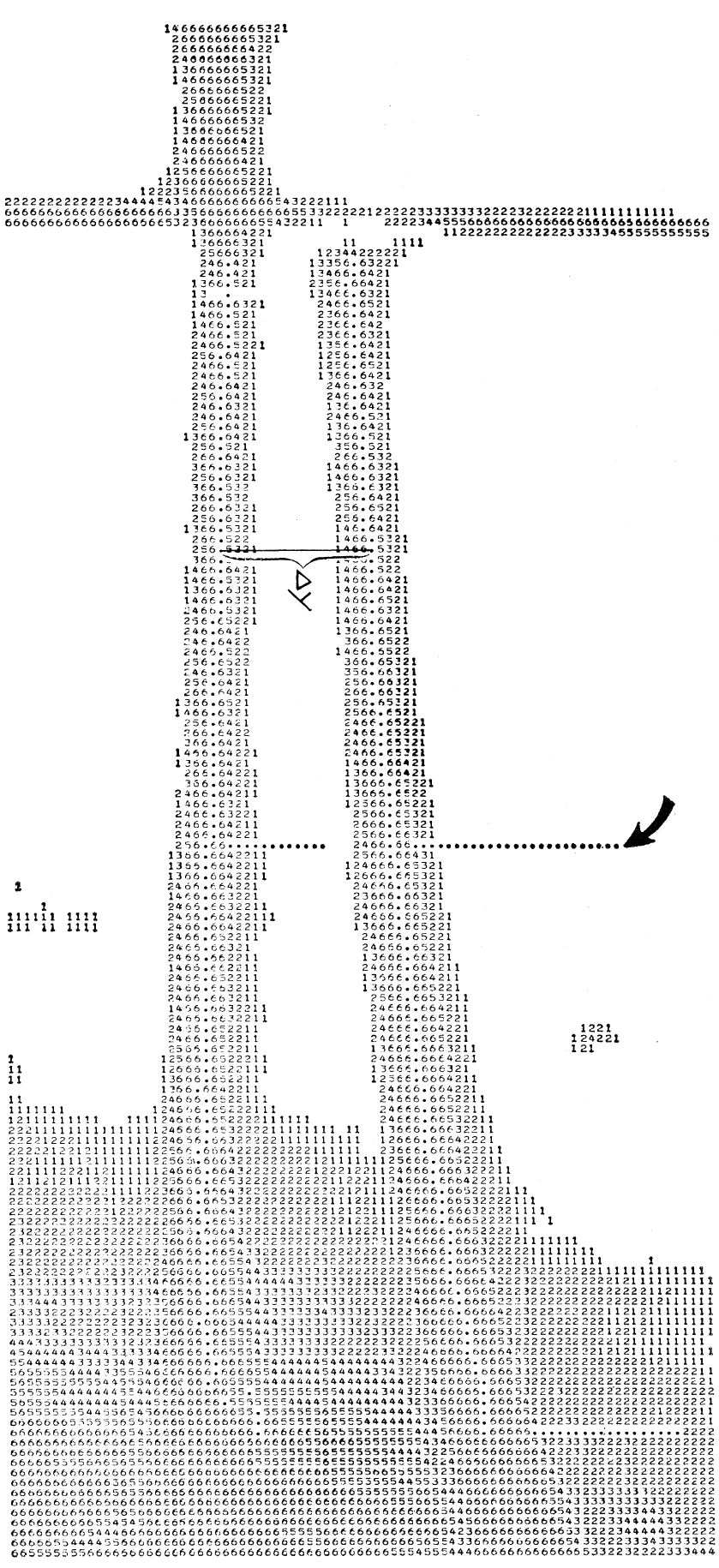
Computer printout of digital-ization of a scanned schlieren photograph. The number at each point represents the density of the corresponding point on the photograph, in one of seven gray levels (the 0-level appears as a blank). The computer measures the magnitudes of delta y, the distance between the two curves at more than 100 points on the curves. The dots represent the "footprints" of the two bugs that were programmed lo perform the analysis. One bug was started at the arrow and moved across until it found the center of the right-hand curve; it then initiated another bug that moved across to find the center of the next curve, the x-axis. The two bugs then marched along their respective curves, measuring the delta-y distance as shown in the diagram.
 Extract: Using Bugsys
Once the entire image is in the memory, the picture is interpreted by a program written in a computer-programming language called BUGSYS (3); the program creates hypothetical "bugs" at points in the picture stored in the memory, which are such that they can read the number corresponding to the gray level at any point and perform simple motions on command - such as moving up, down, left, or right; finding the center of a thick line; or finding the end of a line. Two such bugs were used, acting together, to locate the origin of axes and coordinates of more than 100 pairs of points on the picture, which points represent values for xt and the corresponding delta-y,- between solution and solvent curves on the schlieren image (see Fig. I). This schlieren curve represents the solution of the transport equation. The contrast on the spectroscopic plates is such that the photographic image does not have a sharp black-white edge; it changes gradually from dark to light to dark again. The BUGSYS program determines the gray level of each point of the image and the coordinate value for the center of the line (midway between the locations of points of equal gray level). The pairs of values of the coordinates thus determined are used in the same fashion as would be the data obtained by manual measurement of the spectroscopic plate with a comparator: the measured distances are converted to centimeters and used, together with constants for the temperature, angular vdocily, and partial specific volume and the ideal gas constant, for numerical solution of the transport equation.
The advantage of this method is in reducing time spent on the work to less than 1 second; it also makes it practicable to pool computer programs and algorithms (or soft ware) from several laboratories and to have these used correctly, even though the investigator may not be in constant touch with the computational aspects of the problem. Moreover, one may now obtain many desirable numbers that hitherto were neglected because of lack of time —for example, internal image processing and computational checks, uncertainty to be attached to the final numerical result, and corrections for certain .second-order effects such as compressibility of (he solvent, dependence of the activity of the solute on its concentration, solute-solvent interactions, noninstantaneous acceleration time, Johnston-Ogston effect for heterogeneous systems, elastic rotor stretching, and adiabatic cooling of the rotor during acceleration.
Extract: Disadvatages, conclusions
One disadvantage is that the method requires a photograph of higher quality than is otherwise necessary: background fog, especially nonconstant background fog, cannot be handled by a simple BUGSYS routine. Since the points are the analog solutions of well-behaved continuous functions, it should be possible either to use the first solution as the first step of an iterative solution and reread the plates by use of this knowledge, or to autocorrelate the coordinates of the points. (Ultimately it will be possible to assemble a system such that, if an investigator learns a computer language consisting of six to twelve words with which he can specify a large number of different kinds of calculations that he wishes, he can easily write a program to obtain the results he wants.)
In summary, our method seems feasible as a general approach fo processing schlieren images and to the computation of data measured from them.
in [ACM] CACM 9(02) February 1966 view details
in Rosenfeld et al (eds) "Pictorial pattern recognition" Thompson Washington DC 1969 view details
in Rosenfeld et al (eds) "Pictorial pattern recognition" Thompson Washington DC 1969 view details
in Grasselli, A. (Ed.) Automatic interpretation and classification of images, Academic Press, New York, 1969 view details
The BUGSYS system on the 7094 is based on the [Animated Movie Language by Knowlton]; It can be used for varying types of applications, including the analysis of photomicrographs of neuron dendrites. The concept of the system is the use of a set of figures which are visualized as a family of bugs. A bug can be placed and then moved. It can also change the gray-level value of the spot on which it is located and can lay down a stick across a thick line in a picture as an aid to locating the middle of the line. The PLACE statement assigns a name and initial coordinates to a bug. The MOVE moves it a specified distance either horizontally or vertically. There is a series of test statements which examine the gray-level value of the picture at the location of the bug. The gray-level value may be changed by the change statement.
in Grasselli, A. (Ed.) Automatic interpretation and classification of images, Academic Press, New York, 1969 view details
The paper is richly illustrated, and in general gives a brief overview of the subjects covered. The interested reader can find more detailed information in earlier papers by the authors cited in the bibliography.
in ACM Computing Reviews 11(05) May 1970 view details
in ACM Computing Reviews 15(04) April 1974 view details
The exact number of all the programming languages still in use, and those which are no longer used, is unknown. Zemanek calls the abundance of programming languages and their many dialects a "language Babel". When a new programming language is developed, only its name is known at first and it takes a while before publications about it appear. For some languages, the only relevant literature stays inside the individual companies; some are reported on in papers and magazines; and only a few, such as ALGOL, BASIC, COBOL, FORTRAN, and PL/1, become known to a wider public through various text- and handbooks. The situation surrounding the application of these languages in many computer centers is a similar one.
There are differing opinions on the concept "programming languages". What is called a programming language by some may be termed a program, a processor, or a generator by others. Since there are no sharp borderlines in the field of programming languages, works were considered here which deal with machine languages, assemblers, autocoders, syntax and compilers, processors and generators, as well as with general higher programming languages.
The bibliography contains some 2,700 titles of books, magazines and essays for around 300 programming languages. However, as shown by the "Overview of Existing Programming Languages", there are more than 300 such languages. The "Overview" lists a total of 676 programming languages, but this is certainly incomplete. One author ' has already announced the "next 700 programming languages"; it is to be hoped the many users may be spared such a great variety for reasons of compatibility. The graphic representations (illustrations 1 & 2) show the development and proportion of the most widely-used programming languages, as measured by the number of publications listed here and by the number of computer manufacturers and software firms who have implemented the language in question. The illustrations show FORTRAN to be in the lead at the present time. PL/1 is advancing rapidly, although PL/1 compilers are not yet seen very often outside of IBM.
Some experts believe PL/1 will replace even the widely-used languages such as FORTRAN, COBOL, and ALGOL.4) If this does occur, it will surely take some time - as shown by the chronological diagram (illustration 2) .
It would be desirable from the user's point of view to reduce this language confusion down to the most advantageous languages. Those languages still maintained should incorporate the special facets and advantages of the otherwise superfluous languages. Obviously such demands are not in the interests of computer production firms, especially when one considers that a FORTRAN program can be executed on nearly all third-generation computers.
The titles in this bibliography are organized alphabetically according to programming language, and within a language chronologically and again alphabetically within a given year. Preceding the first programming language in the alphabet, literature is listed on several languages, as are general papers on programming languages and on the theory of formal languages (AAA).
As far as possible, the most of titles are based on autopsy. However, the bibliographical description of sone titles will not satisfy bibliography-documentation demands, since they are based on inaccurate information in various sources. Translation titles whose original titles could not be found through bibliographical research were not included. ' In view of the fact that nany libraries do not have the quoted papers, all magazine essays should have been listed with the volume, the year, issue number and the complete number of pages (e.g. pp. 721-783), so that interlibrary loans could take place with fast reader service. Unfortunately, these data were not always found.
It is hoped that this bibliography will help the electronic data processing expert, and those who wish to select the appropriate programming language from the many available, to find a way through the language Babel.
We wish to offer special thanks to Mr. Klaus G. Saur and the staff of Verlag Dokumentation for their publishing work.
Graz / Austria, May, 1973
in ACM Computing Reviews 15(04) April 1974 view details
in SIGPLAN Notices 13(11) Nov 1978 view details