AMBIT/G(ID:313/amb004)
Ambit symbolic package for graphs
(G for graphs).
Places
- Computer Associates us Research
People:
Related languages
| AMBIT | => | AMBIT/G | Adaptation of | |
| LEAP | => | AMBIT/G | Written using | |
| AMBIT/G | => | AMBIT/L | Restriction of |
References:
in ACM Symposium on "Interactive Systems for Experimental Applied Mathematics", editors Klerer and Reinfelds, Washington, D.C., August 1967 view details
in ACM Symposium on "Interactive Systems for Experimental Applied Mathematics", editors Klerer and Reinfelds, Washington, D.C., August 1967 view details
Introduction
AMBIT/G is a graphical programming language, developed by Christensen, for the manipulation of directed graphs. The data upon which an AMBIT/G program operates 1s a two-dimensional network of nodes and directed links between nodes. Each node in this data graph has an associated shape, and each shape has a number of special points from which links are allowed to emanate. Each of these link departure points (LDP's) may have at most one departing link. An arbitrary number of links may terminate at any node. Each node in the data graph may have a name; no two nodes may have the same name. Each "upstream" node in the data graph (a node at which no links terminate) must have a name.
Like SNOBOL and AMBIT/S, AMBIT/G is a pattern matching language. While SNOBOL and AMBIT/S deal with 1D patterns (strings), AMBIT/G deals with 2D patterns (graphs).
An AMBIT/G program consists of a number of statements in a 2-D graphical form, each specifying
(1) a subgraph to be found in the data graph,
(2) changes to make to the linkages in the data graph if the subgraph is found,
(3) the statement to execute next if the subgraph is found, and
(4) the statement to execute next if the subgraph is not found.
The algorithm for "finding" a subgraph in the data graph is simplified by a requirement that each upstream node in the subgraph have a name.
Since named nodes are unique in the data graph, all upstream nodes in the subgraph can be directly associated with the corresponding nodes in the data graph, and then a node by node match test may be done for downstream nodes . This facilitates very efficient (but restricted) graph matching.
As an example, Fig. 1 shows a typical data graph,

and Fig. 2 shows a typical AMBIT/G statement.

In Fig. 2, the name of the statement is at the top of the picture, and the names of the statements to execute next in case of match success or match failure are at the bottom. The double link indicates a linkage change to make in the data graph if the subgraph matches successfully.
The AMBIT/G language affords an easy and natural way to express algorithms for building and pruning tree structures, garbage collecting a list-structure, maintaining a free-storage allocation facility, etc. Typically, a user's natural view of such data structures and structure manipulation algorithms corresponds with the graphical representations of these in the AMBIT/G language.
Several straight-forward modifications to the original definition of the language (see Reference 1) were made in the course of this work.
(1) Node-shape classes were introduced. This facility allows the user to define a symbol to represent a class of node shapes. He may use such a symbol in a subgraph as a bound variable. Only certain "values" maybe assumed by this variable: nodes from the specified class of node shapes. In the sub graph matching procedure, when a class symbol is encountered in the subgraph, the corresponding node in the data graph is examined. If its shape is a member of the indicated class of node shapes, then the node is "assigned" to the indicated variable, and the matching procedure continues. Other wise, the matching procedure fails. This feature introduces a significant convenience when many near duplicate statements would normally be required.
Figures 3,4, and 5 show an example of the use of node shape classes.


(2) Several special node shapes were introduced. For example, the reserved shape may be used to predicate on the absence of a link from an indicated LDP, or to disconnect a link from an indicated LDP. Fig.6 shows a statement which will succeed only if the indicated LDP does not link to any node;

Fig. 7 shows a statement which will disconnect the indicated LDP if it links to a box.

(3) Away to combine AMBIT/G statements into subroutines was introduced. This led to a facility for graphical specification of control flow linkages between program subparts. One result of this was a careful reformulation of program structure,
A program in the language consists of a control entry point, and a number of calls on a library of subroutines. Each subroutine has a unique n2. A program is represented graphically as a 2-D network of "subroutine-call symbols" and control flow lines . A " subroutine-call symbol" is a box which contains the name of the subroutine and several "control-flow exit points". Fig. 8 shows the graphical representation of a typical program.

Each control-flow exit point may have at most one flow line leaving it. Also, control may leave a subroutine call through only one of its exit points (i.e., parallelism is not allowed). A subroutine call may have an arbitrary number of flow lines entering it (at most one of these may ever be active).
A subroutine may have one of two forms:
(1) a statement
A statement in the language is represented in a 2-D graphical form, specifying
(a) the name of the statement,
(b) a subgraph to be found in the data graph, and
(c) changes to make to the linkages in the data graph if the subgraph is found.
The subroutine-call symbol for a state ment has two control-flow exit points: one to be taken if the subgraph is found (lower left), and one to be taken if the subgraph is not found (lower right). Fig. 9 shows a typical statement and its subroutine call symbol.

(2) a subprogram
A subproqram has a name and a control entry point, and is represented graphically as a two-dimensional network of subroutine call symbols, control flow lines, and "subprogram exit points" . These points correspond to the control flow exit points on the subroutine call symbol for the subprogram. Fig. 10 shows a typical subprogram and its subroutine call symbol.

A subprogram may call other subprograms and may call itself recursively.
A preliminary version of the AMBIT/G language with the extensions outlined above has been implemented on the TX-2 computer. The available facilities on the TX-2 for interactive graphics 4 are well suited for such an implementation.
The overall goal in the work reported here is the creation of an experimental facility for both the development and implementation of AMBIT/G language constructs. Flexibility is of primary importance; modifications and extensions to the implementation should be easy to make. For this reason , the LEAP system was used to create the AMBIT/G facility. LEAP has high-level tools for doing interactive input, display output, and data-structure manipulations. Extract: A User's View
A User's View
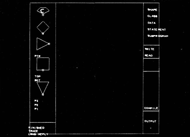
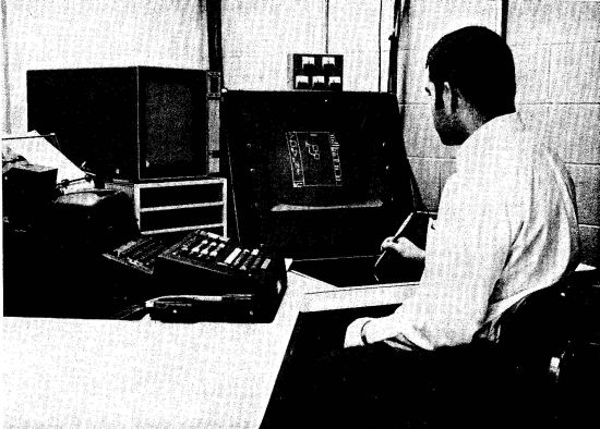
The equipment available to a user at a TX-2 console includes a keyboard and typewriter, a computer-driven display, and a Sylvania Tablet. A user of extended AMBIT/G employs these tools to input and edit his 2-D program and data, to control the execution of his program and to examine output data.
Input
The Sylvania Tablet is the primary input device; it is used to draw in the working area, and point to light targets at the sides of the working area (see Photos 1 and 2).


Drawn characters are analyzed by a character-recognition program, which then dispatches to corresponding action routines. Some drawn characters cause the picture in the working area to be modified; others are interpreted as control commands. For example, a drawn straight line will cause a link segment to be added to a statement in the working area; a drawn "Q" will cause a return to the time-sharing monitor.
Light targets appear at the sides of the working area, and are used either as control commands (targets at the right), or as prototype selection indicators (targets at the left). For example, targets at the right include explicit action commands (e.g. RUN) and definition mode selectors (e.g. SHAPE, DATA, CLASS, STATEMENT, SUBPROGRAM). Targets at the left include small pictures of the defined node shapes.
While a user is working in a definition mode, he deals with pictures. A picture contains either a prototype node shape, a data page, a node shape class definition, a statement, or a subprogram. A picture may be defined, edited, or deleted. A two-dimensional syntax check may be performed on a picture; if there are errors, indicators are displayed at the appropriate places in the working area. For example, a statement picture is checked for dangling links, illegal link sequences, and unreachable nodes.
After a new picture is defined, or after an old picture is edited, the user must point to the FILE light target if he wishes to finalize his work. If he instead attempts a command that would cause the working area to be cleaned, he will be notified, and his command will be ignored. Any subsequent command will be obeyed. This allows the user to easily change his mind and it helps to protect him against inadvertent blunders. If a new prototype node shape is filed, a small picture of it will be appended to the list of light targets at the left of the working area. The user may then type in the name of a new node of that shape. The new prototype node name will appear as a light target below the indicated node shape. If the list of light targets gets too long to fit in the working area, a circular buffer of light targets will be created, and the TURNPAGE light target (at the right) will appear. Pointing to TURNPAGE will cause the "next" portion of the list of prototype node shapes to be shown at the left. When a picture is filed, only graphical information is saved; connectivity information is generated from the graphical information in a separate step (called "acceptance") prior to program execution.
While working on a picture, a user deals with graphical entities. In SHAPE mode, the entities are lines, line endpoints, and LDP indicators. In CLASS, DATA, and STATEMENT modes, the entities are node shapes, link segments , and link segment endpoints . In SUBPROGRAM mode, the entities are subroutine call symbols, subprogram exit points, link segments, and link segment endpoints.
While working on a picture, a user may erase or move any entity. The erase command is simply a drawn scrub mark (ww over the entity. An entity may be moved in the working area either by pointing to it and then pointing to where it should move, or by entering MOVE mode (another light target at the right), and then dragging the entity to its new position with the tablet stylus. Once in MOVE mode, the user may move other entities as well. The user may return from MOVE mode by pointing to the NORMAL light target, also on the right. Whenever an entity is moved, the relevant linkage lines stretch and contract.
While working on a picture, a user may create certain new entities. In SHAPE mode, a drawn line will result in a new line for the shape.
Drawing a small "x" will produce an LDP indicator. In the other definition modes, a drawn line will produce a link segment, complete with arrowhead. In STATEMENT mode, a line drawn with a loop w) will produce a double link segment, with arrowhead. In CLASS, DATA, and STATEMENT modes, the user may point to a node-shape target on the left, then draw a number of "x's" in the working area. Each drawn "x" will cause an instance of the indicated node shape to appear in the picture at the indicated position. In SUBPROGRAM mode, the targets on the left are the names of existing statements and subprograms rather than prototype node shapes. Each drawn "x" will cause the indicated subroutine call symbol to appear at the indicated position. A drawn downward arrow will cause a subprogram exit point to appear near the head of the arrow.
The user may save his work between sessions on the computer; he may give it a name and write it out on his storage area by pointing to the WRITE light target and then typing in the name; he may read in a named program by pointing to the READ light target and then typing in the name.
Acceptance
When a user finishes defining and editing his program and data graph, he may point to the ACCEPT light target. This will cause a final syntax check to be made on all of his input, and all graphical information (positions of link segments and node shape instances, for example) to be processed to yield connection information (a list of nodes, LDP's, and links from LDP's to nodes). If errors are encountered during this process, they are indicated and acceptance is aborted. If the program is fully accepted, it may then be executed by pointing to the RUN light target.
Execution
When an AMBIT/G program is "run", the AMBIT/G system interprets the connection information which was generated when the program was "accepted". This information includes control connection information, which is used to regulate control flow. Statements are executed by first attempting to match the specified subgraph to the current data graph. A successful match will cause indicated linkage changes to be made in the data graph, and then the left (success) control flow path to be taken. An unsuccessful match will simply cause the right (failure) control flow path to be taken. An error is indicated and execution is terminated if a control flow path is a dead end. If the special statement named STOP is encountered, then execution is terminated.
There are several execution control options available as debugging aids. A user may interrupt the execution of his program by pointing to the HELP light target. He may cause his program to be interrupted when a specified statement is executed, or after a specified number of statements are executed. He may cause the name of a specified statement to be printed whenever that statement is executed, or he may request the names of all executed statements to be either printed or displayed in order of execution.
Output
After a program has terminated, or after it has been interrupted, a user may examine the state of the data graph. He does this by pointing to the OUTPUT light target, which causes him to enter OUTPUT mode. The problem of automatically laying out and displaying an entire data graph has been carefully avoided; the user is required to specify small parts of the data graph that he wishes to see, and he is encouraged to aid in the layout of these.
Upon entering OUTPUT mode, the node shape and node name prototypes appear again as light targets on the left. The user may point to a node name prototype, then draw an "x" in the working area. An instance of the indicated named node will appear. The user may then point to an LDP on the new instance. If a link departs from the corresponding LDP in the data graph, both the link and an instance of the node of the end of the link will be displayed. The program will decide where to display the new instance. The user may override this decision when he points to an LDP by immediately drawing a line to a position for the new instance. If a link does not depart from the corresponding LDP in the data graph, a star (*) is displayed on the indicated LDP.
The user may continue to point to other LDP's in the working area, or create instances of other named nodes. He may use special drawn characters to shrink or expand his picture, and translate it up or down, left or right. He may erase (by using a drawn scrub mark) any link or instance in his picture. Any links or instances which are downstream will also be erased.
When the user finishes examining his data-graph, he may return from OUTPUT mode by pointing to the DONE light target. He may resume execution of an interrupted program by pointing to RESUME.
Extract: Internal Representation (LEAP)
Internal Representation
An AMBIT/G program and data graph is represented internally by a LEAP data structure. A brief introduction to LEAP follows .
A LEAP program deals with items, triples, and sets. An item is used to represent either an element in the data structure or an attribute which relates two items. An item may have an associated algebraic datum. A triple is an ordered collection of three items and is usually used to represent a fact of the general form:
(1) ATTRIBUTE . OBJECT = VALUE
(ATTRIBUTE of OBJECT is VALUE.) A set is an unordered collection of items. Examples taken from the implementation follow:
(a) An instance of a node shape in a statement is represented internally by an item having a matrix as its datum. This matrix contains the display coordinates of the instance.
(b) Every instance of a node shape is associated with the node shape proto type by a triple of the form:
(2) SHAPEOF.INSTANCE# = SHAPE#
In (2), SHAPEOF is a declared item, and INSTANCE# and SHAPE# are item type designators; i.e. a triple beginning with SHAPEOF associates a node shape instance with a node shape prototype.
(c) The declared set SHAPES is the set of
all node shape prototypes.
The item type designators and prototype triples for selected parts of the internal representation of a program and data graph are tabulated below. Certain item type designators need further explanation.
(a) LINE#
Links in data pages and in statements are composed of lines. A line in a statement may be double (have the DOUBLE property).
(b) DTAPG#
At ACCEPT time, all data pages are merged to generate the initial data graph. Overconstraints are noted and reported.
(c) ILDP#
At ACCEPT time, each LDP of each instance in the structure is examined to determine if it is the start point of a link. If so, an ILDP (Instance Link Departure Point) is generated and associated (via triples) with the instance and with the indicated LDP on the node shape prototype.
Extract: Aspects of the Design
Aspects of the Design
Several design decisions were made after implementing and experimenting with various alternative designs; convenience for the user was the primary consideration in these decisions.
No push-buttons or toggle switches are used; we felt that these are confusing and distracting. Use of a simple drawn character or a light target is easier.
The user does not draw node shape instances, but rather points to the desired shape and then draws an "x" at the desired position. The special symbols that the user may draw are simple enough to recognize easily, and are quite convenient to use.
There are two ways to move an entity in the working area: by drawing a "move character" or by entering "move mode" and dragging the entity with the tablet stylus. Experience has indicated the necessity for both. The move character is useful for a single move command if the destination is clear. "Move mode" is useful if many moves are to be performed or if the user wants response as the entity moves.
When the user draws in the working area, he is drawing on a square grid. That is, the end-points of all lines and the centers of all node instances will be automatically put on the nearest grid point. This feature makes neat drawings and does not restrict the user appreciably, He may be reasonably sloppy in drawing a link, for example, and the startpoint will be made to coincide with a nearby LDP. There are two grid sizes: one for SHAPE mode, and one for the other modes. When drawing a SHAPE declaration, it is convenient to work on a fairly gross grid (the working area has 16 grid points on a side in SHAPE mode; in the other modes, it has 64 grid points on a side).
No automatic graphical syntax check is made while the user is defining his program and data graph. The syntax of his data graph and program pictures is checked only upon explicit request from him or at ACCEPT time. This allows him to file away a partially completed picture. The system is considerably simplified by this feature because it needs only to remember a list of picture parts and their positions until ACCEPT time. Also, a change made to a node shape declaration has no subtle effect on the connectivity of a program statement in which there is an instance since no connectivity information is kept.
The program for displaying the modified data graph was made as simple as possible, primarily because any automatic layout facility is very difficult to implement and would not be significantly better than the simple scheme.
Light targets are displayed only when they are relevant; this helps to minimize confusion and provides an indication of the state of the system.
Extract: Conclusion
Conclusion
The preliminary system has been used to implement two examples .
(1) The list-structure garbage collection program used as the example in Reference 1.
(2) A reductions-analysis program for parsing an input string from a simple grammar and building the computation tree.
The experience of using the system in timesharing on TX-2 has pointed out some major inadequacies in the environment. The programs are fairly large and typically require fast response and a small time slice. When the time-sharing system has a medium to heavy load, response lag-time increases to 10 to 20 seconds. Typically, a user must wait about 15 seconds after drawing a symbol (or pointing to a light target) before he can draw the next symbol. For this kind of application on TX-2 either the environment in time-sharing must be reorganized or the machine must be used in dedicated mode.
The poor response in time-sharing is caused primarily by the need to swap users in and out of core. The response lag-time increases dramatically as soon as the total active user core requirement exceeds available core. This problem is aggravated by two things.
(1) The swapping mechanism being used is very slow (it is a FASTRAND II drum which is meant to be used for file storage).
(2) People tend to write very large programs (the Lincoln Reckoner is a notable exception) because there is no convenient way to segment programs. For example, the LEAP compiler does not compile relocatable code nor will it compile sub routines separately from a main program. There is no relocatable loader facility; even the assembler assembles non-relocatable code.
Other factors which contribute to system overhead are:
(1) the main frame is used to process interrupts and track the two tablets. If both tablets are active, this overhead is very large.
(2) The display structures for all active dis plays reside in core; the display generator steals memory cycles to refresh the displays.
In the course of this work, several ideas for further extensions to the language have arisen. For example, a way to manipulate algebraic values is needed. Also, a facility for linking to programs written in other languages is desirable. Other suggestions include the following:
(1) display a selected portion of the data graph dynamically as the program is executed.
(2) Display the main control flow diagram and blink the subroutine call symbols which are active as the program runs.
(3) Improve the character recognition program to the point where it is easier to use than the keyboard, and eliminate the keyboard.
(4) Take advantage of the two-dimensional control flow specification to allow con current control flow paths (parallelism).
The programming work was done entirely in time-sharing using the LEAP language. Both of these tools were found to be crucial to the development. Machine availability for editing, debugging, and experimenting was very important; a timesharing console was perfectly adequate and readily available. The facilities in LEAP for expressing interactive input and display output were found to be very powerful and very easy to use. The ability to make changes easily to the implementation made much of the experimentation feasible; a program written in LEAP is relatively easy to read and understand.
The language forms for building and manipulating a data structure in LEAP were used extensively to create and process the internal representation of an AMBIT/G program and data graph. It was unnecessary to design and implement an elaborate list structure to house the internal representation; we were free to concentrate on the design of interactive features because we were insulated from many of the intricate details of the data structure implementation. Inefficiencies have been introduced into the AMBIT/G system by the use of LEAP; these are noticeable only when a large computation has to be made (when checking, accepting or running). The programs could be made considerably smaller and faster if they were re-coded in machine language, but this would require much work and would remove much flexibility. Acceptance time could be decreased by maintaining partial connectivity information as pictures are input. This would complicate the input programs, but might improve overall response
in Donald E. Walker, Lewis M. Norton (Eds.): Proceedings of the 1st International Joint Conference on Artificial Intelligence IJCAI-69, Washington, DC, May 1969. William Kaufmann, 1969 view details
in IEEE International Convention and Exposition, New York, March 1971 view details
Abstract: INTRODUCTION
AMBIT/L is a list-processing programming system. It applies to essentially non-numeric programs which operate on data structures of moderate or extreme complexity. This applications area includes artificial intelligence, graphics, algebraic manipulation, and such software as compilers, interpreters, simulators, and editors.
A remarkable and unique feature of AMBIT/L is its use of two-dimensional diagrams. Both the data and the program are represented by diagrams in which conventional text plays only a secondary role. The data diagram depicts the current relations between variables and values, and lines in this diagram move as program execution proceeds. The program diagram uses patterns of data in order to reference and modify the data. These diagrams are not informal aids or supplementary documentation; they are the representations used for communication with the computer. The value of a diagram in almost any context is familiar. But, in computer programming, the use of diagrams for data can have quite spectacular effects.
In diagrammatic form, a collection of data can become an almost machine-like object, changing frequently in certain places but relatively fixed in others. An apparently difficult algorithm can be made easy by the selection of an appropriate structuring and constraint of the data. The development of AMBIT/L has included some pleasant surprises . The expected heavy demand for an elaborate graphics terminal did not arise; instead, an ordinary teletype (or line printer) proved adequate to "draw" working diagrams using the ordinary characters. Problems with formatting were eliminated by simple conventions which just happened to work for AMBIT/L. And the language structure seemed to flourish generally in the absence of the problems of delimiting, separating, and grouping which afflict textual programming languages.
In terms of more familiar languages, AMBIT/L can be viewed as operating on list-structured data resembling that of LISP; incorporating the pattern-matching style of programming characteristic of SNOBOL; adopting the block-structured program framework of ALGOL 60; and providing trapping and interrupt facilities found in PL/I.
Another view of AMBIT/L is to consider it a specialized version of AMBIT/G, a language of much greater theoretical interest and, for the present, of lesser practical value . This view is both historically and logically correct. AMBIT/L followed AMBIT/G by about two years and a future objective is to derive AMBIT/L from AMBIT/G by a completely formal sequence of "constraints" on the program and data of AMBIT/G.
The AMBIT/L programming system has been operational on a Digital Equipment Corporation PDP-10/50 time-sharing computer since September 1969. The system includes its own diagram generator, compiler, link editor, interpreter, and debugging facility .
AMBIT/L has been used to implement its own compiler (which was bootstrapped), its own debugging system, and certain of its built-in functions such as those for input-output and for long-integer arithmetic. But the most notable application of AMBIT/L has been to IAM.
IAM is a large and complex system for interactive algebraic manipulation. IAM is written entirely in AMBIT/L. As of July 1970, it is composed of 301 separately compiled AMBIT/L program blocks; it has block nesting to a depth of 13 levels; has a listing of about 1500 pages of two-dimensional diagrams; and compiles to reentrant interpretive object code about 40,000 36-bit words long.
This paper describes those aspects of AMBIT/L which are unusual and important. It provides an outline of the language, some of the design motivation, and some examples. It is an appropriate basis for evaluation of the language; but it should, ideally , be supplemented by a few moderately large example programs. There are no prerequisites for the paper; but the reader without experience with ALGOL 60 and LISP may find certain passages difficult.
in [ACM] Proceedings of the Second Symposium on Symbolic and Algebraic Manipulation, March 23-25, 1971 Los Angeles (SYMSAM 71) view details
in [ACM] Proceedings of the Second Symposium on Symbolic and Algebraic Manipulation, March 23-25, 1971 Los Angeles (SYMSAM 71) view details
An important [data structure diagrams] language is Ambit/G
[Christensen, 1968]. The operands of this language
are directed graphs naturally diagrammed in two dimensions.
An operation on these structures consists of a search for a subgraph that matches a specified
pattern graph, followed by a replacement of the
matching subgraph with a given graph. The language
conveniently describes involved data structures and
their transformations much as many of us do with
pencil and paper (or chalk and blackboard) for communication
between people. Text can appear in the
boxes of a diagram, but the text itself is strictly
one-dimensional. In its original form Ambit/G was
a human translated language, although it has been
implemented as a pen language using a tablet for
input and scope for output [Rovner and Henderson,
1969]. A specialized version of Ambit for list processing
is known as Ambit/L [Wolfberg, 1972]. This
language also, like many others, is actually independent
of its implementation, but for our purposes
is a typewriter based, human translated language
which makes use of teletype or printer twodimensional
feedback. Christensen [Christensen,
1971] says that the diagram sketch to encoded source
translation (the two-dimensional to one-dimensional
translation) is "simple and is done on the fly.
in Proceedings of the SIGPLAN symposium on Two-dimensional man-machine communication 1972 , Los Alamos, New Mexico, United States view details
in Proceedings of the International Conference on Reliable software Los Angeles, California 1975 view details
Resources
- TX-2 and Sylvania Tablet using Ambit/G
- Ambit/G in operation