Knowlton, K. C. "A computer technique for producing animated movies" pp67-87
view details
Extract: Introduction
Introduction
This paper describes a computer technique used for the production of animated diagram movies.* This technique ? as implemented with the IBM 7090 computer and the Stromberg-Carlson 4020 microfilm recorder ? involves the basic steps of coding and checkout, production computer run, and optical printing from the master film thus produced.
Programs are coded in the "movie language" to be described, a language which has been developed entirely within the framework of MACRO FAP. They are checked out, without producing film, through examination of picture samples printed on the standard output printer.
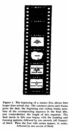
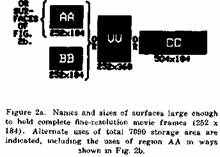
After checkout, the production run produces a magnetic tape which instructs the 4020 in exposing a master film, such as that shown in Fig. 1. Each frame of this film is made of a rectangular array of tiny characters produced by the 4020 charactron tube used in the typewriter mode. The recording camera is slightly defocussed, thereby turning the finely structured characters into contiguous blobs of different intensities, depending upon the characters used. Each picture thus consists of a rectangular array of blobs on a raster either 126 wide and 92 high or, for finer resolution, 252 wide by 184 high. Figures 2a, 2b, and 3 of this paper were actually made by this system ? operating in the fine-resolution mode ? as if they were to appear as scenes in a movie.
The master film contains only one picture for each sequence of identical frames of the final movie; a comment above this picture indicates the length of the sequence. The "stretching out" of the master is done by optical printing at a movie laboratory, where standard processes are also used for editing, adding a sound track, and making work prints and final prints.
Internal Representation of Pictures
The movie programmer imagines that pictures exist within the 7090 on rectangular surfaces ruled off in squares, each square containing a number from 0 to 7. Pictures are created and manipulated by changing the patterns of numbers in the squares. During output these patterns of numbers are interpreted as spots of appropriate shades of grey, according to a programmer-specified transliteration. Fine-resolution pictures are produced by "aiming" the output routine at a subarea 252 squares wide and 184 squares high; for coarse-resolution pictures the output routine is aimed at an area 126 squares wide and 92 squares high.
The total storage area within the 7090 corresponds to two complete fine-resolution movie frames. This area may be used in different ways: as two independent surfaces, each just large enough for one complete movie frame, or as one surface twice as wide or one surface twice as high. These possibilities are indicated in Fig. 2a which gives the names of these surfaces and their sizes in squares. Every square of a surface is assigned x and y coordinates, the bottom left-hand corner square of every surface having the coordinates x = 0, y = 0.
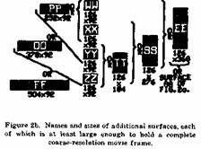
There are still other sizes and shapes of surfaces which can be used for complete coarse-resolution frames (or for parts from which fine-resolution pictures will be composed by copying). These surfaces, with their names and sizes, are shown in Fig. 2b. Their use precludes the simultaneous use of surfaces AA, VV, or CC.
Extract: The Programming Language
The Programming Language
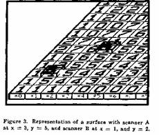
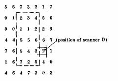
The programmer's basic conceptual framework includes a number of scanners which he imagines to be sitting on various squares of the surfaces (see Fig. 3). Scanners can intercommunicate, and each can read the number it is sitting on, can write a new number into this square, and can move right, left, up, or down any integral number of positions to a new square. Scanners may also convey information ? by virtue of their positions or the numbers on which they sit ? to the subroutines of the movie system. There are 26 scanners in all, each named by a different letter of the alphabet.
The language by which the computer is programmed to make movies may be divided into two parts. The first and historically older part consists of those instructions for drawing and changing pictures by explicit manipulation of scanners. This part, the "scanner language," may be used for other purposes than movie making. It may be used, for example, to draw flowcharts or schematic wiring diagrams which are represented within the computer by two-dimensional arrays of the digits 0 through 7.
An example of an instruction in the scanner language is
than) scanner C, or that scanner A is sitting on a number Equal to 7
Then the following operations are performed
scanner A moves To the same surface and the same square as scanner B, scanner A moves Up 2 squares, and scanner A Writes the number 3, and control then goes to the line of coding labeled LOC5. If none of the three elementary conditions is satisfied, no operations are performed and control goes to the next line of coding.
The scanner language permits a large number of different elementary tests on the positions of scanners and on the numbers on which they sit. There are also a large number of elementary operations for moving scanners and for changing the numbers on which they sit. A complete list of these basic tests and operations, and the flexible formats in which they may be used, is given in Appendix A. A concise summary of the scanner language appears there in Tables A.1 and A.2.
The other part of the movie language may be called the "movie language proper." It consists of more powerful instructions which in general compile into calls to subroutines written primarily in the scanner language. (These subroutines actually use an additional set of 26 scanners which the programmer need not know about.) Instructions of the movie language proper fall logically into three categories: instructions for controlling the output or temporary storage of pictures, instructions for performing drafting and typing operations, and instructions for modifying the contents of rectangular areas. These categories will be discussed briefly in turn.
The outputting of movie frames (i.e., the writing of the tape which will control the S-C 4020) is performed by an internal "camera" subroutine. The subroutine has many modes of operation, which are determined by "camera settings." One setting "aims" the camera at all of or part of a surface; another specifies how many frames of the final film are to be produced for every frame of the master film. A third setting specifies the transliteration from digits 0 through 7 to the typeable characters of the 4020 charactron. Other settings specify what output the camera routine should produce on the normal printer, for monitoring purposes. Facilities are also available for temporarily storing entire contents of surfaces on a disc file. Up to 440 complete fine-resolution movie frames may be stored on the disc at any one time.
The facilities for drafting include the ability to draw straight lines, arcs, and arbitrary curves. These lines may be made to appear instantaneously in the movie, or they may be made to appear gradually as they are drawn Lettering may be done by "typing" letters of six different sizes, the smallest letters each covering an area 4 squares wide and 5 high, the largest covering an area 15 squares wide and 21 high.
Finally, the entire contents of a surface or a rectangular subarea may be changed in many ways The area may be "painted" by filling all of its squares with one particular digit, or another area of similar size and shape may be copied into it. The contents of the area may be shifted an integral number of positions up, down, right, or left, or they may be "expanded" (by repeating rows or columns) or "squashed" (by deleting rows or columns) in any of the four directions Certain local operations may be performed throughout the area, such as adding incremental layers to regions defined by a certain number, or rounding sharp coiners There are operations which approximate the effect of a zoom lens by enlarging or reducing by an integral factor the pattern of numbers within a rectangular area while the camera routine is putting out pictures of the intermediate states of the picture There is also a facility for "dissolving" one picture onto another by sprinkling the new numbers onto the old ones, again while the camera routine is outputting the intermediate states of the dissolve
The movie language proper is described in detail in Appendix B. A programming example, involving instructions both of the scanner language and of the movie language proper is presented in Appendix C. This sample program was actually the program used to produce Fig 2a of this paper.
Extract: Uses of the Movie System
Uses of the Movie System
This movie language may be used to produce many types of simple animated movies It may be used, for example, to produce visual displays for psychophysical experiments, or to produce a more common type of movie such as the expository educational film
The system may also be used to convert the output of computer performed experiments into visual displays For example, the person experimenting with heuristics for automatic layout of printed circuits may wish to watch in a movie
the computer's attempts to search efficiently for wire paths
Costs for producing movies by this means are low, and movies can also be produced quickly, primarily because only a few people are involved Simple educational movies cost a few hundred dollars per minute, with the cost split approximately equally three ways programmer's time and overhead, computer time, and standard movie laboratory operations
Much of the power of the movie system as implemented derives from the fact that it has been constructed entirely within the framework of MACRO FAP The instructions of the scanner language and of the movie language proper are actually macro instructions As such, they may be interspersed with instructions of the basic FAP language or, more important, with higher order macro-instructions which the programmer has defined in terms of the original movie instructions Appendix C contains examples of such higher-order macros which were developed, in some cases because they were more powerful, and in others because they more exactly matched the requirements of a specific job
Extract: The Scanner Language
The Scanner Language
The scanner language is that part of the movie language by which the programmer explicitly performs tests and operations on the 26
scanners?those reading and writing heads illustrated in Fig 3 which scan and operate on two-dimensional arrays of numbers This appendix describes the formats and uses of scanner language instructions, Appendix B describes the more powerful movie instructions which constitute the "movie language proper" An example of programming with both kinds of instructions is presented in Appendix C
Scanner Initialization
A scanner, before being used, must be initialized by an instruction with the special format
PLACE sc,surf,x,y (eg PLACE D,BB,92,5)
which has the effect of placing scanner sc on the surface surf at coordinates x,y. The scanner may be any one of the 26 available, A,B, ,Z, and the surface may be any one of those illustrated in Figs 2a and 2b The coordinates must refer to a square which is actually on the surface the programmer should note that the bottom left square coordinates (0,0) and the top right square of, say, a 252 X 184 surface, has coordinates (251, 183)
General Instruction Formats
Scanner instructions are generally expressed m terms of elementary tests on positions of scanners and the numbers in the squares they are sitting on, and in terms of elementary operations directing scanners to move or write new numbers into these squares
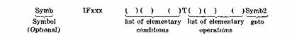
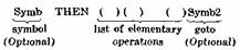
Instructions ? or lines of coding ? are of two basic types unconditional and conditional The
and it contains the following parts
1 In the location field of the card, an optional FAP symbol which is not a single letter or double letter (the symbols A,AA, B,BB, Z,ZZ have been pre-empted by the movie system)
2 In the operation field of the card, the macro name THEN
3 In the variable field of the card, a list of operations, followed by an optional single symbol indicating where control is to go after the operations have been performed If there is no goto, control passes to the next line of coding If there is a goto, the entire list of operations may be missing The length of the list is limited by the restriction that the operation and goto must appear on one card from columns 16 through at most column 72
The conditional instruction is similar in format except that preceding the list of operations there appears a list of elementary conditions followed by the delimiter 'T', and that the name of the macro-instruction indicates which of four logical functions on the conditions must be satisfied in order that the operations be performed
If the list of operations is null, the 'T' is omitted and a goto must appear Again, the length of the lists is limited only by the requirement that the list of conditions must start in column 16 and the instruction may extend at most through column 72 of the same card
Each of the 4 MACRO names requires satisfaction of a different logical function of the conditions, as follows
IFANY, satisfied if any of the elementary conditions is satisfied
IF ALL, satisfied if all of the elementary conditions are satisfied
IFNONE, satisfied if none of the elementary conditions are satisfied
IFNALL, satisfied if not all of the elementary conditions are satisfied
unconditional instruction may be illustrated schematically as
In each case, if the compound condition is satisfied, then the indicated operations are performed and if there is a goto, control goes to the indicated point in the program, otherwise to the next line of coding. If the compound condition is not satisfied, no operation is performed and control goes to the following line of coding.
In addition to the five basic macro-instructions, the following synonyms are built into the system:
ANY, synonym for IFANY
ALL, " " IFALL
NONE, " " IFNONE
NALL, " " IFNALL
IF, " " IFALL
NOT, " " IFNONE
EITHER, " " IFANY
BOTH, " " IFALL
ELSE, " " THEN
The first four of these are simply abbreviated notations to facilitate programming. The others enable the program to be more easily
read and understood. IF and NOT are suggested in place of IFALL and IFNONE, respectively, where there is just one elementary condition. Likewise, EITHER and BOTH are suggested in place of IFANY and IFALL, respectively, where there are two elementary conditions. ELSE is suggested in place of THEN when it follows a conditional instruction that has a goto.
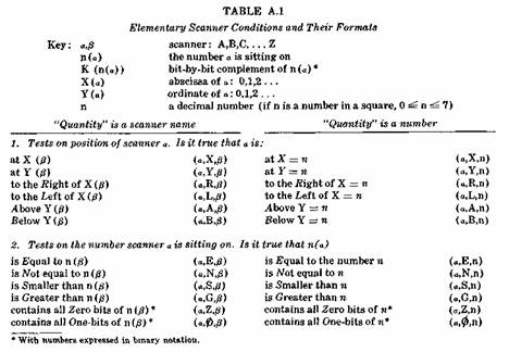
Elementary Conditions or Tests
An elementary condition is a simple test performed on the position of a scanner or on the number this scanner is sitting on. Every elementary condition is written as a triplet of arguments separated by commas and delimited by parentheses. It has the form
(scnr,rel,quant)
where scnr is a single-letter name of a scanner, rel is a single letter designating a particular relation, and quant specifies either directly or indirectly, the quantity or coordinate involved
in the test. If quant is a number it specifies the quantity directly; if quant is a letter than it specifies the scanner whose number or position is involved in the test. A complete list of tests and the letter by which they are designated appears in Table A.1.
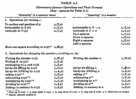
Extract: Elementary Operations
Elementary Operations
An elementary operation, like an elementary condition, is written as a triplet of arguments, separated by commas and delimited by parentheses, and has the form
(scnr.op.quant)
Here scnr is the single-letter name of the scanner which performs the operation, op is a single letter designating the operation to be performed, and quant generally specifies directly or indirectly a quantity involved in the operation: as in elementary tests, a number specifies the quantity directly, whereas a letter specifies the scanner whose number or position is to be used. One exception is the operation
(a,Z,b)
which specifies that both scanners a and b are to exchange numbers, i.e., each writes the number that the other was just sitting on.
A list of elementary operations appears in Table A.2. It should be noted that certain operations require that the quantity involved always be indicated directly as a number, whereas certain other operations require the quantity to be specified indirectly by the name of a scanner.
It should also be noted that there is no particular relation between the interpretation of a specific triplet as a test and the interpretation of the same triplet as an operation. For example the triplet
(B,A,6)
interpreted as a test means "Is scanner B above y = 6?", whereas as an operation it means "The number that scanner B is sitting on should have ANDed onto it the number B (i.e., its low order bit should be forced to zero)." Whether a triplet is to be interpreted as a test or an operation is determined by its position in the line of coding.
The available operations permit scanners to be moved beyond the limits of their surfaces as defined by Figs. 2a and 2b; special consideration should be given to the results of such operations. The surfaces of Fig. 2a act as helices, such that a single step "right" from the right column of the surface places the scanner on the leftmost column of that surface but one row below where it started. Conversely, a step left over the edge places it on the right edge one row above where it started. Motion above and below the top and bottom edges is legal, but the scanners will perform a "no-operation-and-continue" instead of altering any "numbers" that they might be sitting on there. Furthermore, the programmer should be aware that the y-coordinate is treated modulo 215, so that after a step down from y = 0, a test on its position will result as if the scanner were at y = 32,767.
The connectivity of the surfaces of Fig. 2b is similar to that of surfaces in Fig. 2a except that after stepping over the right edge of the surface, a scanner enters a no-man's-land a few squares wide; after successive steps through this region, the scanner appears, as in the case of the other surfaces, on the left edge, one row below the one it started on.
Another precaution regarding the use of the operations of Table A.2 concerns the case in which two or more scanners are sitting on the same square, as they would be, for example, after an operation of the form
(a,T,b)
If one of the scanners changes the number on the square in any way, the other scanners on that same square do not "know" that the number has been altered, and subsequent tests or operations involving the number under one of the other scanners may yield an erroneous result. In general a scanner updates its memory of the number it is sitting on only when it
moves to a square or when it itself changes this number. "Moving" a scanner a to its own position by the operation
(a,T,a)
will always properly update a's conception of the number it is sitting on.
Finally, a scanner's memory may be deliberately set to a number which has no relation to the number it is sitting on by the last operation of Table A.2:
(a,S,b) or (a,S,n)
Extract: Subroutines
Subroutines
In order to perform a subroutine beginning at symbolic location sub, the special triplet
(QQ,P,sub)
is inserted as an ordinary triplet in a list of elementary operations. This special operation saves on a pushdown list the location at which the program was operating, and it transfers control to the subroutine.
Exit from a subroutine is accomplished by use of the special goto which is identically
QQ
Since subroutine returns are recorded on a pushdown list, a subroutine may use itself, provided that the programmer has in some way prevented indefinite recursion into the routine.
Double-letter "scanners"
In addition to the 26 scanners A through Z, there is a special double-letter scanner sitting on the upper right hand corner of each surface. The name of each such special "scanner" is identical with the name of the surface. These scanners may not be moved but they may be used to write numbers on their particular squares. Their names may also be used as the "quantities" in tests and operations on regular scanners. For example, there is a scanner BB sitting on the upper right hand corner of surface BB at (251,183) and the instruction
IF (A,X,BR)T(A,T,BB)
would function the same as the instruction
IF (A,X,251)T(A,Y,183)
The double-letter scanners may also be used on the same basis as single-letter scanners for specifying areas to which the higher order operations of Appendix B are to be applied.
Extract: The Movie Language Proper
The Movie Language Proper
In addition to the scanner instructions of Appendix A, the movie programmer may use the more powerful instructions of the "movie language proper," described below. These are, in general, macro-instructions which compile into calls to subroutines which themselves are written mostly in the scanner language.
The movie instructions fall naturally into four categories, including instructions for
controlling output of pictures and temporarily storing pictures and retrieving them from the disc file,
performing drafting and typing operations,
performing "instantaneous" operations on the contents of rectangular area or surfaces, and
performing "dynamic" operations on the contents of rectangular areas or surfaces.
An instantaneous operation is one which is performed and completed between output of adjacent frames of film, whereas a dynamic operation is one which is performed gradually while several frames of pictures are being output by the "camera" output routine.
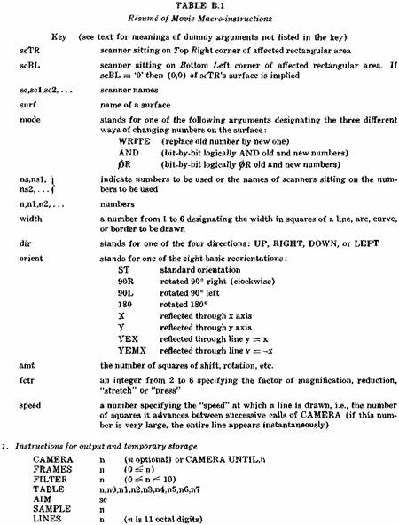
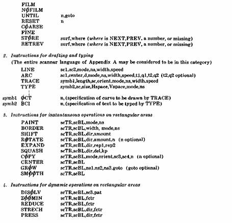
These four groups of macro-instructions will be discussed in turn. The format of each instruction will be illustrated and described in terms of dummy arguments and in most instances an example of the use of the instruction will be given. A resume of all macro-instruction formats is given in Table B.1, which also contains a list of the more common dummy arguments used to describe these instructions.
1. Instructions for Output and Temporary Storage
An output routine or "camera" within the 7090 is used to write information on the magnetic tape which is later used to direct the S-C 4020 in exposing film. The camera routine is initiated by the instruction
CAMERA n (n optional)
(e.g. CAMERA 3)
where n is the intended number of identical frames to be produced in the final film. Only one frame is produced by the 4020, with the number n printed just above this frame. If n is not specified in the CAMERA call, then the number used is that last specified by the setting
FRAMES n
(e.g. FRAMES 2)
This setting is useful for controlling the apparent speed at which dynamic operations are performed, since the subroutines of the system which perform dynamic operations contain CAMERA calls without specification of n. In the event that the specified or effective n is zero, the camera call is ineffective, and no picture is output.
Besides the FRAMES setting, there are several other settings which control the operation of the camera routine. Camera settings, to be discussed in turn, include
FRAMES
(how many identical frames in final movie?)
AIM
(what surface area to output?)
FINE or COARSE
(what resolution?)
FILTER
(what transliteration during output?)
SAMPLE
(how often to monitor results on printer?)
LINES
(which lines of picture to print when monitoring?)
FILM or NOFILM
(film output, or just monitor output?)
These settings must be made before the first CAMERA call, but they may be changed at any later point in the program.
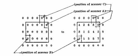
The surface area to be output is determined by the position of that scanner sc specified in the last previous setting of the form
AIM sc
(e.g. AIM BB)
(or AIM A)
The top right corner of the picture which is output by a CAMERA call is the current position of that scanner specified by the AIM setting. If the scanner moves, the camera tracks the scanner.
The output mode (coarse or fine) is determined by which of the settings,
FINE or COARSE
occurred last. The setting FINE specifies that henceforth and until encountering the next COARSE, the area to be output is a rectangular array of squares 252 wide and 184 high. The setting COARSE specifies that henceforth and until the next FINE, the area to be output is an array 126 wide and 92 high In this case, the spots are displayed at twice the spacing for FINE output in order to fill the complete movie frame.
It will normally be the case that the picture on film is to be composed of other charactron characters than the digits 0 through 7 This requires transliteration during output, specified by the setting
FILTER n (0 ± n ^ 10)
(eg FILTER 5)
where n is either 0, specifying no transliteration, or a number from 1 to 10 specifying one of ten available transliteration tables Each table thus used may be set up or later changed by a command
TABLE n,nO,nl,n2,n3,n4,n5,n6,n7
(eg TABLE 5,60,15,14,72,13,16,54,53)
which causes table n to transliterate 0 into nO, I into nl, 2 into n2, etc The characters which may be used for output on the charactron are any of the sixty-four octal characters 0 through (77)8 except (12)8, (52)8, and (56)8 The specific example above gives a recommended grey scale, transliterating 0 into blank (60) 8 1 into apostrophe (15) 8, 2 into quote (14), 3 to degree sign (72) 8 4 to equal sign (13) 8 5 to delta (16) 8, 6 to asterisk (54) 8, and 7 to dollar sign (53) 8 which is the darkest typeable character on the charactron.
In addition to him output, printed output may be produced for monitoring purposes The setting
SAMPLE n
(eg SAMPLE 24)
says that printed output is to be produced for every n"' frame of the final movie, except that this output will be produced at most once in any one CAMERA call Thus if the sampling rate is 24 and the instruction, CAMERA 150, is encountered, only one printed output is produced during this operation, labeled with the beginning and ending frame numbers of the corresponding sequence of identical frames in the final movie The part of the frame which is to appear in the printed output is predetermined by the bit pattern of the 11-digit octal number, n in the setting,
LINES n
(eg LINES 1400000003)
The first octal digit is 1 or 0, stating that lines x = 91 and x = 90 of a COARSE picture should or should not be printed, each successive bit states whether or not the next 3 lines should be printed In the example given, only the top 5 lines and the bottom 6 lines would be printed If the output mode is FINE, then only the odd columns of the corresponding odd-numbered rows are printed If the above sample LINES setting were used for fine-resolution output, then odd-numbered positions of rows 183, 181, 179, 177, 175, 11, 9, 7, 5, 3 and 1 would be printed (counting the bottom line as line zero)
The actual production of film is enabled or disabled by the instructions
FILM or NOFILM
each of which compiles into a single machine instruction Common practice is to begin every program with this sequence of instructions, and to test the program m this form, producing only the printed output for monitoring purposes When the program has been checked out, a production run is performed in which a correction card replaces the NOFILM instruction with a NOP machine instruction.
The system contains a counter which counts frames of the final movie This counter may be interrogated, and flow of control directed by the branch
UNTIL n.goto
(e g UNTIL 2400.AGAIN)
which causes control to go to the indicated goto if the current frame count is below the specified number n A special format for the CAMERA call also uses the frame counter
CAMERA UNTIL,n
(e g CAMERA UNTIL.2496)
This call directs the camera routine to produce one frame, as does a normal call, but in this case the number in the frame line ? specifying how many times this frame is to be repeated in the final movie ? is made just large enough to bring the frame count up to the specified n The frame counter may be reset by the program to any n by the command
RESET n
(e g RESET 4800)
Operations and tests involving the frame counter are intended primarily to facilitate synchronization of the movie with a sound track which is added later by traditional methods.
In addition to putting out pictures on film, contents of entire surfaces may be temporarily stored on and retrieved from the disc file There are 440 available storage areas on the disc, numbered 1 through 440, each capable of storing the entire contents of any surface except surfaces VV or CC Storing of surface <ruif is accomplished by the instruction
STORE surf,where (where is n,NEXT,PREV, or null)
(eg STORE AA.150)
and the picture is retrieved by the instruction
RETREV surf,where (where is n,NEXT,PREV, or null)
(eg RETREV AA.PREV)
In either case, the storage area where may be specified explicitly by a number, or implicitly by three other possibilities if where is missing in the call, the last area used in a STORE or RETREV command is used, NEXT implies the next higher area than the last one used, and PREV implies the next lower area than the last one used The surfaces VV or CC can be effectively stored by storing the contents of both AA and BB, since the latter occupy the same internal 7090 storage space For example, contents of surfaces VV (or CC) may be stored in areas 150 and 151 by the sequence
STORE AA.150 STORE BB,NEXT
and they may then be retrieved by the sequence
RETREV BB
RETREV AA.PREV
One precaution must be taken after retrieval of a picture a scanner a now sitting on this surface may not act as if it were on the corresponding new number until it is first "moved" by some such scanner instruction as (a,T,b) or
(a,X,a) Or UY,a)
2 Instructions for Drafting and Typing
The instructions for drafting have the names LINE, ARC, and TRACE, the one instruction for typing is called TYPE These are all dynamic operations in the sense that while each is being executed it is interrupted periodically to allow the camera routine to output pictures For the TYPE instruction, the interruption occurs after every large character (made up of a rectangular matrix of numbers) has been typed, and the camera routine may be rendered ineffective by a previous setting 'FRAMES 0' For the drafting operations, the interruption occurs every time the line being drawn has advanced another n squares, where n is specified in the instruction as the "speed" at which the line is to be drawn In this case, the interruption is avoided, or it is rendered ineffective, by a very high speed (e g 5000) or by a previous setting 'FRAMES 0'
An approximation to a straight line is drawn from scanner sc1 to sc2 by the instruction
LINE sc1, sc2, mode, ns, width, speed
(eg LINE A, B, WRITE, 5, 3, 9)
The line is drawn by using the number ns (or the number that ns is sitting on if ns is a scanner name) " if mode is WRITE, this number is used to replace the numbers on affected squares, whereas if mode is OR or AND, the new number is ORed or ANDed, bit by bit, with the previous number in each affected square The line is drawn by an imaginary stylus which moves by stepping either horizontally or vertically to the adjacent square which lies closest to the ideally straight line On each square thus traversed, an approximately circular dot of diameter width is centered, and a picture is produced after advancing each n squares along the line, where n is the desired speed.
An arc is drawn in a manner similar to the drawing of a line, by the instruction
where the arguments mode,ns,width, and speed have the same meaning as for LINE. The arc begins at the position of scanner scl, and proceeds with scanner accent as its center, in direction d, which is CW for clockwise or CCW for counterclockwise. The arc is terminated when the drawing stylus, which itself may be thought of as a scanner, satisfies the joint condition, expressed in scanner language,
(stylus,tl,ql) (stylus,«2,g2)
or when it satisfies simply the first condition if the second condition is not given in the ARC instruction. If the terminating condition is not satisfied within 1000 elementary steps, the program stops. In the specific example above, an arc of width 5 is initiated at scanner A and is drawn about scannerB as center in a counterclockwise direction at speed of 12, by 0Ring the number 6 onto affected squares. The arc is terminated when the drawing stylus is at the same height as scanner B and right of scanner B.
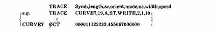
A curve of arbitrary shape may be traced by an instruction of the form
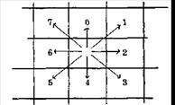
where mode,ns,width and speed have the same meanings as for LINE. The argument length is the length of the curve to be drawn, expressed in elementary steps from one square to the next, sc is the scanner at which the curve is to start, and orient is one of the eight possible reorientations of the basic curve (see the Key in Table B.I). Symb is a FAP symbol indicating the location at which a description of the basic curve is given in terms of a sequence of incremental steps. Each step is here specified by one of eight octal digits which stand for the eight possible directions for these steps:
In the specific example above, if the original surface contained only zeros, and if on output zeros are transliterated to blanks and 2's to dots than the result would be
If the same curve (with the same description) had been drawn in the YEMX orientation (reflected through the line y = ? x) it would have started with a straight section going left and then would have spiralled counterclockwise..
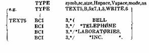
The operation of "typing" in the movie language is done by affecting appropriate patterns of squares. The general form of the typing instruction is
where symb is a FAP symbol identifying the description of the text to be typed, sc is the scanner specifying the position of the bottom left hand corner of the first character to be type, and size is one of the following sizes of characters which may be typed:
4x5 (4 squares wide, 5 high)
5x7 (5 squares wide, 7 high)
7x10 (7 squares wide, 10 high)
8x11 (8 squares wide, 11 high)
10x14 (10 squares wide, 14 high)
15x21 (15 squares wide, 21 high)
The argument Hspace specifies the horizontal spacing in squares between the characters of a line, whereas Vspace specifies the number of squares of vertical spacing between successive lines. The mode may be AND, OR, or WRITE as with the drafting operations, but the programmer must note that only those squares corresponding to the body of the letter are affected: background areas, such as the center of a '0' or the entire area of a blank are unchanged regardless of the mode used. The argument ns is either the number to be used in changing affected squares, or the name of scanner sitting on the number to be used. The description of text to be typed is written out on FAP BCI cards. All of the 48 standard IBM Hollerith characters may be typed. The following special sequences, all starting with '*', have the indicated meanings for the typing routine:
*. stop typing
* ( shift to upper case (affects typing of letters only)
*) shift to lower case (affects typing of letters only)
*L where L is any letter: Type this letter in upper case, then shift to lower case
* return carriage: Return to starting point of previous line, then go down letter height plus vertical spacing
** type the character '*'
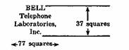
In the specific case of the example illustrated, the result would appear approximately as follows:
Other examples of typing operations appear in Appendix C.
3. Instructions for Instantaneous Operations on Rectangular Areas
The contents of rectangular areas may be altered by any of a large number of instantaneous operations?operations which appear to be performed instantaneously in the movie because their respective subroutines contain no CAMERA calls. The formats and uses of these instructions are described in the following paragraphs. In all eases, the rectangular areas to be changed are specified by the positions of scanners. The dummy argument "scTR" in a format statement stands for "scanner defining the Top .Right corner of the area." The dummy argument "scBL" means "either the name of a scanner defining the Bottom Left corner of the area or else '0', meaning x = 0, y = 0 of the surface that scanner scTR is on."
A rectangular area may be "painted"?every square changed by using the same number? by the instruction
PAINT scTR,scBL,mode,ns
(e.g. PAINT ZZ,0,WRITE,0)
where mode, as before, is AND, 0R or WRITE, indicating whether the change is to be accomplished by ANDing, 0Ring, or replacement, respectively and ns is either the number to be used or the name of a scanner sitting on the number to be used. In the example above, the entire surface ZZ is "cleared" to zeros.
A rectangular border of any thickness may be produced just within the periphery of the rectangular area by the instruction
B0RDER scTR,scBL,width,mode,ns
(e.g. B0RDER A,B,9,0R,A)
where width is the thickness of the desired border, mode and ns indicate the manner in which numbers are to be changed and the number to be used, as in the case of PAINT.
The contents of a rectangular area may be shifted up, right, down or left any number of positions?up to the dimension of the area in this direction?by the instruction
SHIFT scTR,scBL,dir,amt
(e.g. SHIFT AA,0,UP,36)
where ami is the number of squares of shift and dir is the direction of shift, UP.RIGHT, D0WN, or LEFT. As a result of the shift operation, material is lost at one edge of the rectangular area and the "vacated" area is filled by repeating the original row or column just within the edge that contents of the area were shifted away from.
The material within a rectangular area may be "rotated," as if around a cylinder, by the instruction
R0TATEscTR,scBL,dir,amt,n(noptional)
(e.g. ROTATE C,D,LEFT,5)
The effect is the same as for SHIFT except that the material which is lost at one edge is introduced at the opposite edge. Furthermore, if n is given, the material which "goes around the back" to be reintroduced is transliterated according to transliteration table n. This table must have been previously established by a TABLE instruction such as is used to specify transliteration during output, but only the three lowest-order bits of the new numbers can be used for the ROTATE transliteration.
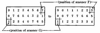
The pattern of numbers within a rectangular area may be "expanded" upward or downward by duplicating certain rows, or it may be expanded to the right or left by duplicating certain columns. The instruction
EXPAND scTR,scBL,dir,repl,rep2
(e.g. EXPAND F,G,RIGHT,2,3)
causes the material to be expanded in the direction dir (UP, RIGHT, D0WN, or LEFT) by starting at the edge row or edge column opposite the direction of expansion and repeating the first row or column repl times, the next row or column rep2 times, the next repl times, etc., until the entire rectangular area has been refilled. The sample EXPAND instruction above would change the pattern
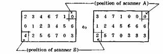
The pattern of numbers in a rectangular area may also be "squashed" toward one edge by depleting certain rows or columns and by repacking the remaining numbers. The instruction
SQUASH scTR,scBL,dir,deI,kp
(e.g. SQUASH A,B,LEFT,1,2)
performs such an operation by starting at the edge specified by the direction dir and alternately deleting del columns (rows) and keeping kp columns (rows). The remaining columns (rows) are closely packed and the vacated area is filled by duplicating the original column (row) just within the edge from which the motion has occurred. The sample instruction above would change the pattern
A rectangular area may be filled or changed by "copying" from another area. This is accomplished by the powerful and versatile instruction
COPY scTR,scBL,mode,orient,sc3,sc4,n
(n optional) (e.g. COPY A,B,WRITEI90L,C,D)
Here, as before, scTR and scBL define the affected area, sc3 is a scanner on this same surface (it may in fact be either scTR or scBL) and sc4 is a scanner on the surface from which material is being copied. The precise area to be copied is visualized as follows: the entire surface being copied from is reoriented according to orient (see Key in Table B.I) and then supe-imposed on the surface to be changed in such a position that sc3 and sc4 coincide. It is that area which now falls on the rectangle defined by scTR and scBL which is used: this area is first transliterated according to table n if n is given, and then it is ANDed, ORed or written into the rectangle, accordingly as mode is AND or OR or WRITE. Peculiar and unexpected patterns may result if the two rectangular areas involved are overlapping areas on the same surface, unless they are exactly the same area and orient is ST. The above sample instruction involves a 90-degree rotation to the left (counterclockwise). Thus, if scanner D is located as shown:
the effect would be to change the rectangular area
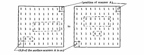
Lines of typed text, such as lines of a movie title, may be centered in a rectangular area by the instruction
CENTER scTR,scBL
(e.g. CENTER A,0)
For this instruction to be effective, all squares bordering on the edge of this area must contain the same number, called the "backgound" number. The complete background consists of all rows containing only the background number and, for each horizontal stripe not thus included, it also contains the widest possible rectangle on the right and on the left which contain only background numbers. Remaining sub-areas thus delimited are called "lines of text." The CENTER operation identifies all lines of text, centers each such line horizontally, and moves all lines together by a shift-up or shift-down to make top and bottom background stripes equal. Thus it would change the area
Two different local operations can be performed throughout a rectangular area. Both consume a relatively large amount of computer time (ca. 10 seconds for the surface AA); therefore the area to which they are applied should be judiciously limited. The first local operation,
GR0W scTR,scBL,nsl,ns2,ns3,goto
(go to optional)
(e.g. GROW XX,0,2,3,5,AGAIN3)
changes every number nsl which is next to an ns2 into an nsS. The number ns2 must also be within the area and it must in each instance be immediately above, below, right of or left of the number to be changed. The numbers nsl, ns2 and nsS must be three different numbers, and each may be either given explicitly or specified as the name of the scanner sitting on the number to be used. If the instruction contains a goto, then on completion of the operation control passes to the goto if at least one such number was changed. Two GROW instructions are commonly used in a loop which causes the region defined by two numbers gradually to "grow" into the region defined by a third by alternately adding incremental layers first of one of its numbers and then of the other. If the loop contains a CAMERA call, the growth process is seen in the movie.
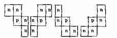
The other local operation, which has the effect of removing sharp corners, is
SMOOTH scTR,scBL
(e.g. SMOOTH A.B)
The operation proceeds by identifying every instance of the four patterns
where all four n s in a pattern must be the same number. For each instance thus found, the p is changed to an n.
4. Instructions for Dynamic Operations on Rectangular Areas
Dynamic operations on rectangular areas are those for which a series of pictures are output, according to current camera settings, while the operation is proceeding. As in the case of instantaneous operations on rectangular areas, the affected area must be designated by two scanners (or by one scanner and '0', meaning 0,0 of that scanner's surface).
A rectangular area may have another area of similar size and shape "dissolved" onto it while a series of 36 pictures is being produced. The instruction is
DISOLV scTR,scBL,sc3,pat
(e.g. DISOLV XX,0,ZZ,F)
where scanner scS indicates the top right corner of the area of similar size and shape which is to be dissolved onto the area specified by scTR and scBL. The dissolve is accomplished by dividing the area, which must be at least 6x6 squares in sizes, into 6x6 subareas ? possibly with oddly shaped rectangles at the left and bottom. Between any two successive pictures of the dissolve, an additional number of the old picture is replaced by the corresponding number from the new picture in each 6x6 subarea. The order in which new numbers are thus introduced is specified by the parameter pat which must be one of the following:
F fade: quasi-random order SI spiral in (simultaneously in all 6x6 sub-areas)
SO spiral out (simultaneously in all 6x6 sub-areas)
R wipe to right (simultaneously in all six-column-wide sections)
L wipe to left (simultaneously in all six-column-wide sections)
A "zoom" effect may be approximated by gradually magnifying horizontally and vertically, by an integral factor, the pattern of numbers within a rectangular area. This is accomplished by the instruction
ZOOMIN scRT.scBL.fctr
(e.g. ZOOMIN YY,0,3)
where fctr is the magnification factor, an integer from 2 to 6. During the ZOOMIN operation, the approximate center of the pattern is fixed and material is lost off all four edges.
An approximate inverse of ZOOMIN is accomplished by the instruction
REDUCE scTR,scBL,fctr
(e.g. REDUCE A,B,5)
where fcti is the factor of reduction, again an integer from 2 to 6. Reduction is accomplished by repeated deletions of rows and columns and by repacking toward the center those remaining. Vacated area around the periphery is filled in by repetitions of rows and columns originally just within the periphery of the area.
A unidirectional magnification is accomplished by the instruction
STRECH scTR,scBL,dir,fctr
(e.g. STRECH A,B,UP,2)
which holds one edge of the pattern fixed and "stretches" the pattern ? by duplicating rows or columns ? in the indicated direction until (l/fact)th of the original pattern covers the entire area, with each of these rows (columns) repeated fctr times'. The direction dir must be UP, RIGHT, D0WN, or LEFT, and the factor fctr must be an integer from 2 to 6.
Finally, an approximate inverse of STRECH is provided by the instruction
PRESS scTR,scBL,dir,fact
(e.g. PRESS ZZ,0,DOWN,3)
which causes the contents of the area to be compressed against one side of the area ? by deletion of rows or columns and repacking in the direction dir. The vacated area is filled with repetitions of the row or column just within the edge from which motion occurs. As before, dir must be UP, RIGHT, DOWN, or LEFT, and fctr is the factor of compression, and integer from 2 to 6.
in [AFIPS JCC 25] Proceedings of the 1964 Spring Joint Computer Conference SJCC 1964 view details
R. Moore; R. S. Ledley; M. Belson; J. D. Jacobsen "Ultracentrifuge Schlieren Photographs: Automatic Analysis" Science, New Series, Vol. 152, No. 3728. (Jun. 10, 1966), pp. 1509-1511. view details
Abstract: Schlieren photographs can be digitized and stored in a computer's memory. A computer program then interprets and measures the Schlieren curve and calculates molecular properties.
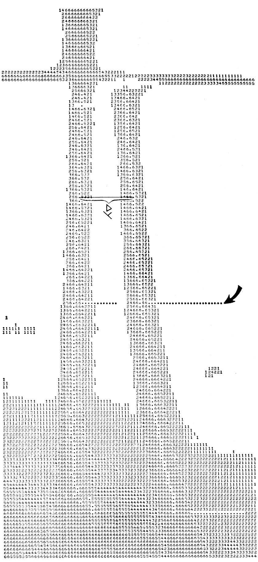
Extract: Figure 1 Computer printout of digital-ization of a scanned schlieren photograph. The number at each point represents the density of the corresponding point on the photograph, in one of seven gray levels (the 0-level appears as a blank). The computer measures the magnitudes of delta y, the distance between the two curves at more than 100 points on the curves. The dots represent the "footprints" of the two bugs that were programmed lo perform the analysis. One bug was started at the arrow and moved across until it found the center of the right-hand curve; it then initiated another bug that moved across to find the center of the next curve, the x-axis. The two bugs then marched along their respective curves, measuring the delta-y distance as shown in the diagram.
Extract: Using Bugsys Once the entire image is in the memory, the picture is interpreted by a program written in a computer-programming language called BUGSYS (3); the program creates hypothetical "bugs" at points in the picture stored in the memory, which are such that they can read the number corresponding to the gray level at any point and perform simple motions on command - such as moving up, down, left, or right; finding the center of a thick line; or finding the end of a line. Two such bugs were used, acting together, to locate the origin of axes and coordinates of more than 100 pairs of points on the picture, which points represent values for xt and the corresponding delta-y,- between solution and solvent curves on the schlieren image (see Fig. I). This schlieren curve represents the solution of the transport equation. The contrast on the spectroscopic plates is such that the photographic image does not have a sharp black-white edge; it changes gradually from dark to light to dark again. The BUGSYS program determines the gray level of each point of the image and the coordinate value for the center of the line (midway between the locations of points of equal gray level). The pairs of values of the coordinates thus determined are used in the same fashion as would be the data obtained by manual measurement of the spectroscopic plate with a comparator: the measured distances are converted to centimeters and used, together with constants for the temperature, angular vdocily, and partial specific volume and the ideal gas constant, for numerical solution of the transport equation. The advantage of this method is in reducing time spent on the work to less than 1 second; it also makes it practicable to pool computer programs and algorithms (or soft ware) from several laboratories and to have these used correctly, even though the investigator may not be in constant touch with the computational aspects of the problem. Moreover, one may now obtain many desirable numbers that hitherto were neglected because of lack of time —for example, internal image processing and computational checks, uncertainty to be attached to the final numerical result, and corrections for certain .second-order effects such as compressibility of (he solvent, dependence of the activity of the solute on its concentration, solute-solvent interactions, noninstantaneous acceleration time, Johnston-Ogston effect for heterogeneous systems, elastic rotor stretching, and adiabatic cooling of the rotor during acceleration.
Extract: Disadvatages, conclusions One disadvantage is that the method requires a photograph of higher quality than is otherwise necessary: background fog, especially nonconstant background fog, cannot be handled by a simple BUGSYS routine. Since the points are the analog solutions of well-behaved continuous functions, it should be possible either to use the first solution as the first step of an iterative solution and reread the plates by use of this knowledge, or to autocorrelate the coordinates of the points. (Ultimately it will be possible to assemble a system such that, if an investigator learns a computer language consisting of six to twelve words with which he can specify a large number of different kinds of calculations that he wishes, he can easily write a program to obtain the results he wants.) In summary, our method seems feasible as a general approach fo processing schlieren images and to the computation of data measured from them.
in [AFIPS JCC 25] Proceedings of the 1964 Spring Joint Computer Conference SJCC 1964 view details
Ledley, R. S. et al "Automatic Determination of Mitotic Index" pp99-104
view details in Rosenfeld et al (eds) "Pictorial pattern recognition" Thompson Washington DC 1969 view details
Ledley, R. S. et al "The Case of the Touching and Overlapping Chromosomes" pp 87-98 view details in Rosenfeld et al (eds) "Pictorial pattern recognition" Thompson Washington DC 1969 view details
Ledley, Robert S.; and Rotolo, Louis S. "Application of pattern recognition to biomedical problems" pp323-362. view details in Grasselli, A. (Ed.) Automatic interpretation and classification of images, Academic Press, New York, 1969 view details
Pavlidis, T. review of Ledley et al 1970 view details in ACM Computing Reviews 11(05) May 1970 view details

 Extract: Using Bugsys